
Different Types of PCBs
Printed Circuit Boards (PCBs) are essential components of modern electronic devices. They provide mechanical support for electronic components and establish electrical connections between them through conductive copper tracks. From smartphones and computers to industrial control systems, automotive electronics, and medical equipment, PCBs play a critical role in the design and operation of electronic products.
There are different types of PCBs, each designed to meet specific requirements related to circuit complexity, flexibility, component density, operating conditions, and manufacturing costs. Understanding the different types of PCBs helps electronics engineers, product designers, and manufacturers select the most suitable board for their applications.
In this article, we will explore the major types of printed circuit boards, their construction, advantages, disadvantages, and common applications.
What Is a Printed Circuit Board (PCB)?
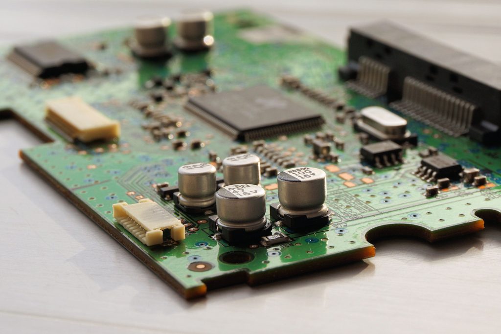
A Printed Circuit Board (PCB) is an insulating board containing conductive pathways, typically made of copper, that connect electronic components. These pathways, commonly called traces, carry electrical signals and power between components.
A typical PCB consists of several layers, including a substrate, copper conductors, solder mask, and silkscreen markings. The substrate provides mechanical strength and electrical insulation, while copper traces establish the required electrical connections.
Depending on the application, PCBs may contain a single copper layer, multiple copper layers, flexible materials, or specialized substrates designed to withstand high temperatures or support high-frequency signals.
Different Types of PCBs
PCBs can be classified according to their number of conductive layers, physical construction, flexibility, material composition, and intended application.
The following sections explain the most common PCB types used in electronic product development.
1. Single-Sided PCB
A single-sided PCB, also known as a single-layer PCB, contains a conductive copper layer on only one side of the insulating substrate. Electronic components are generally mounted on the opposite side, with their electrical connections established through copper tracks.
Single-sided PCBs have a relatively simple construction and are among the most economical types of printed circuit boards to manufacture.
Advantages of single-sided PCBs:
- Low manufacturing cost.
- Simple design and fabrication process.
- Easy inspection and troubleshooting.
- Suitable for straightforward electronic circuits.
Disadvantages:
- Limited routing space.
- Less suitable for complex circuits with many components.
- Circuit layouts may require more board area.
Applications: Single-sided PCBs are commonly used in LED lighting, simple power supplies, basic consumer electronics, calculators, and straightforward control circuits.
For beginners learning PCB design software such as KiCad, a single-sided PCB is an excellent starting point because it introduces schematic design, component footprints, copper routing, and design rule checking without excessive complexity.
2. Double-Sided PCB
A double-sided PCB contains copper layers on both sides of the insulating substrate. Conductive connections between the two sides are typically established using plated through-holes called vias.
Compared with single-sided boards, double-sided PCBs provide more routing flexibility and allow designers to accommodate a greater number of components in a smaller area.
Advantages of double-sided PCBs:
- Greater routing flexibility.
- Higher component density.
- More compact circuit layouts.
- Suitable for moderately complex electronic designs.
Disadvantages:
- Higher manufacturing cost than basic single-sided PCBs.
- More complicated routing and troubleshooting.
- Requires careful consideration of vias and electrical clearances.
Applications: Double-sided PCBs are widely used in embedded systems, industrial controllers, automotive electronics, instrumentation, communication equipment, and electronic power control circuits.
For example, an STM32-based controller with a temperature sensor, MOSFET fan driver, voltage regulator, and programming interface may benefit from a double-sided PCB when a single-sided layout becomes difficult to route.
3. Multilayer PCB
A multilayer PCB contains three or more conductive copper layers separated by insulating materials. Common configurations include four-layer, six-layer, eight-layer, and higher-layer-count boards.
The internal copper layers can be used for signal routing, ground planes, and power distribution. These boards are particularly useful when a design requires high component density, controlled impedance, or improved electromagnetic compatibility.
Advantages of multilayer PCBs:
- High component density in a compact area.
- Better options for power and ground distribution.
- Improved signal integrity when designed correctly.
- Reduced routing congestion.
- Support for complex electronic systems.
Disadvantages:
- Higher manufacturing and design costs.
- More complex fabrication and testing.
- Difficult to repair internal-layer faults.
Applications: Multilayer PCBs are used in smartphones, computers, networking equipment, advanced embedded systems, telecommunications hardware, and high-performance computing devices.
For example, a high-speed processor board may use dedicated ground and power planes to improve signal return paths and reduce unwanted electrical noise.
4. Rigid PCB
A rigid PCB is manufactured using a solid substrate that maintains its shape during normal operation. Common materials include FR-4, a glass-reinforced epoxy laminate widely used in electronic products.
Rigid PCBs are among the most common printed circuit boards because they offer mechanical stability, reliable component mounting, and compatibility with established manufacturing processes.
Advantages of rigid PCBs:
- Good mechanical stability.
- Broad availability and manufacturing support.
- Suitable for through-hole and surface-mount components.
- Available in single-sided, double-sided, and multilayer configurations.
Disadvantages:
- Cannot bend during normal operation without risking damage.
- May require additional connectors or cables between separate assemblies.
- Can occupy more space in products with complex shapes.
Applications: Rigid PCBs are used in desktop computers, televisions, industrial automation equipment, power supplies, household appliances, and embedded control systems.
It is important to understand that rigidity and layer count are different classification criteria. A rigid PCB can be single-sided, double-sided, or multilayer.
5. Flexible PCB
A flexible PCB, commonly called an FPCB or flex PCB, uses a bendable insulating substrate, often made from polyimide. Its construction allows the circuit to bend or fold within specified mechanical limits.
Flexible PCBs are especially useful when electronic connections must fit into compact, curved, or moving assemblies.
Advantages of flexible PCBs:
- Can fit into irregular or confined spaces.
- Reduce the need for separate wires and connectors.
- Can reduce weight and assembly volume.
- Support dynamic movement when designed for flexing.
Disadvantages:
- Can be more expensive than conventional rigid boards.
- Require careful mechanical and electrical design.
- Repeated bending can cause conductor fatigue if the design is unsuitable.
Applications: Flexible PCBs are used in smartphones, cameras, wearable electronics, medical devices, displays, printers, and compact consumer products.
For example, a flexible circuit may connect a display to the main electronic assembly in a compact device where a conventional rigid board would not fit.
6. Rigid-Flex PCB
A rigid-flex PCB combines rigid circuit-board sections with flexible circuit sections within a single integrated assembly. The rigid areas support components, while the flexible areas provide electrical connections between sections.
This construction can eliminate some cables, connectors, and separate interconnecting boards.
Advantages of rigid-flex PCBs:
- Reduced connector count.
- Compact and lightweight construction.
- Better integration of complex electronic assemblies.
- Potentially improved reliability by eliminating certain cable connections.
Disadvantages:
- Higher design and manufacturing costs.
- More demanding mechanical design requirements.
- Repair and replacement can be more difficult.
Applications: Rigid-flex PCBs are used in aerospace electronics, medical instruments, advanced cameras, military electronics, and compact products requiring reliable interconnections.
Rigid-flex designs are particularly useful when a product contains several rigid electronic sections that must be connected through a limited amount of space.
7. High-Frequency PCB
High-frequency PCBs are designed for circuits operating at radio frequencies (RF), microwave frequencies, or other frequencies where signal propagation, dielectric properties, and transmission-line effects become important.
These boards may use specialized laminates with carefully controlled dielectric properties and low signal losses. Materials from manufacturers such as Rogers are used in certain high-frequency applications, although the appropriate material depends on the design requirements.
Advantages of high-frequency PCBs:
- Can provide low signal loss when appropriately designed.
- Support controlled-impedance transmission lines.
- Enable reliable operation in RF and microwave circuits.
Disadvantages:
- Specialized materials can be expensive.
- Fabrication tolerances may be more demanding.
- Layout and measurement require RF engineering knowledge.
Applications: High-frequency PCBs are used in radar systems, antennas, satellite communications, wireless communication equipment, RF amplifiers, and microwave devices.
For example, an RF circuit operating at several gigahertz may require careful control of trace width, dielectric thickness, grounding, and impedance to achieve the intended electrical performance.
8. High-Thermal-Conductivity PCB
High-thermal-conductivity PCBs are designed to manage heat generated by electronic components. They may use specialized dielectric materials, metal-core construction, or other thermal-management features to transfer heat away from critical components.
A metal-core PCB commonly uses an aluminum or copper base with an electrically insulating dielectric layer and conductive copper circuitry.
Advantages:
- Improved heat dissipation in suitable designs.
- Can reduce component operating temperatures.
- Supports compact products with high thermal loads.
Disadvantages:
- Higher cost than standard FR-4 boards in many applications.
- Requires careful electrical insulation and thermal design.
- Metal-core construction can limit conventional routing and via options.
Applications: These PCBs are commonly used in high-power LED lighting, automotive lighting, power electronics, and equipment that generates significant heat.
The choice of PCB depends on the amount of heat generated, the thermal resistance of the complete assembly, the mounting arrangement, and the operating environment.
9. High-Density Interconnect (HDI) PCB
High-Density Interconnect (HDI) PCBs use advanced manufacturing techniques to accommodate more connections within a smaller area. They commonly employ finer traces and spaces, smaller vias, and microvias.
Microvias are small-diameter connections between adjacent or nearby conductive layers. HDI technology can allow designers to route dense component connections efficiently, particularly when using fine-pitch surface-mount components.
Advantages of HDI PCBs:
- High routing density.
- Compact and lightweight circuit assemblies.
- Support for fine-pitch components.
- Greater design flexibility in space-constrained products.
Disadvantages:
- Higher manufacturing costs.
- More complex fabrication requirements.
- Requires detailed design rules and manufacturing coordination.
Applications: HDI PCBs are widely used in smartphones, tablets, compact computing devices, medical electronics, and advanced communication products.
HDI is not simply another name for a multilayer PCB. It refers to a high-density interconnection approach that can be implemented in boards with different layer counts.
10. Aluminum PCB
An aluminum PCB is a type of metal-core PCB that uses an aluminum base to help transfer heat away from electronic components. It typically includes a copper circuit layer and an electrically insulating dielectric between the circuit and the metal base.
Aluminum PCBs are especially useful in lighting and power applications where thermal performance is a major design consideration.
Advantages of aluminum PCBs:
- Effective heat spreading for suitable applications.
- Good mechanical support.
- Often suitable for high-power LED assemblies.
- Can improve thermal performance compared with a basic board construction.
Disadvantages:
- Less versatile for some complex multilayer layouts.
- Requires suitable electrical insulation.
- Not necessarily the best choice for every high-temperature or high-power application.
Applications: Aluminum PCBs are commonly used in LED panels, automotive lighting, streetlights, power modules, and other thermally demanding electronic products.
Although aluminum PCBs are sometimes discussed separately from other PCB types, they are a specific form of metal-core PCB.
11. Ceramic PCB
Ceramic PCBs use ceramic substrates such as alumina or aluminum nitride instead of conventional organic materials such as FR-4. These materials can provide high thermal conductivity, electrical insulation, and stability under demanding operating conditions.
The specific performance depends on the ceramic material, conductor system, fabrication process, and assembly design.
Advantages of ceramic PCBs:
- High thermal conductivity in suitable ceramic materials.
- Good electrical insulation.
- Strong dimensional and thermal stability.
- Suitable for demanding power and high-temperature applications.
Disadvantages:
- Higher manufacturing costs.
- Brittle substrate materials.
- Specialized fabrication and assembly requirements.
Applications: Ceramic PCBs are used in power electronics, high-power LED modules, RF devices, aerospace systems, and specialized industrial equipment.
Ceramic substrates can be particularly valuable when efficient heat transfer and electrical insulation must be achieved in a compact assembly.
12. Thick-Copper PCB
Thick-copper PCBs use copper layers that are substantially thicker than those found in many standard circuit boards. They are designed to support high current, improve current-carrying capacity, and manage heat in suitable applications.
The required copper thickness depends on current levels, permissible temperature rise, trace geometry, and the surrounding thermal environment.
Advantages of thick-copper PCBs:
- Support higher currents when appropriately designed.
- Can reduce conductor resistance.
- Improve heat distribution in certain layouts.
- Allow power and control circuits to be integrated.
Disadvantages:
- Higher manufacturing cost.
- More demanding etching and fabrication processes.
- Thick conductors can complicate fine-pitch routing.
Applications: Thick-copper PCBs are used in motor controllers, battery management systems, power converters, industrial power supplies, and automotive power electronics.
For a high-current fan controller or DC power-conversion circuit, copper thickness and trace width should be selected based on the actual current and thermal requirements rather than relying on a generic trace-width value.
Comparison of Different Types of PCBs
The following table summarizes the major PCB types and their typical uses.
| PCB type | Main characteristic | Common applications |
|---|---|---|
| Single-sided | One copper layer | Simple circuits and LED lighting |
| Double-sided | Copper on both sides | Embedded controllers and instrumentation |
| Multilayer | Three or more copper layers | Computers and communication systems |
| Rigid | Solid, non-flexible substrate | Consumer electronics and industrial controls |
| Flexible | Bendable substrate | Wearables and compact devices |
| Rigid-flex | Combines rigid and flexible sections | Aerospace and medical electronics |
| High-frequency | Designed for RF and microwave performance | Antennas and radar |
| High-thermal-conductivity | Designed for improved heat transfer | Power electronics and LEDs |
| HDI | Fine routing and high interconnection density | Smartphones and compact electronics |
| Aluminum | Metal-core thermal construction | LED lighting and power modules |
| Ceramic | Ceramic insulating substrate | High-power and specialized electronics |
| Thick-copper | Increased copper thickness | Motor drives and high-current circuits |
These categories are not mutually exclusive. For example, a PCB can be rigid, multilayer, HDI, and designed for high-frequency operation at the same time.
How to Choose the Right PCB Type
Selecting the right PCB type is an important part of electronic product development. The choice affects manufacturing costs, electrical performance, mechanical reliability, thermal management, and ease of assembly.
Consider the following factors when selecting a PCB.
1. Circuit Complexity
Simple circuits may work well on single-sided PCBs, whereas more complex designs may require double-sided or multilayer construction. The number of components, required connections, and routing constraints should guide the selection.
2. Available Space
Products with strict size limitations may benefit from multilayer or HDI PCBs. Flexible and rigid-flex designs can be useful when the board must fit into curved or irregular spaces.
3. Electrical Requirements
Operating frequency, voltage, current, signal integrity, electromagnetic compatibility, and isolation requirements all influence PCB selection. RF circuits may need specialized materials, while high-current circuits may require wider traces or thicker copper.
4. Thermal Management
Components such as power transistors, voltage regulators, LEDs, and motor drivers generate heat. Depending on the thermal load, designers may need thermal vias, copper planes, heat sinks, metal-core PCBs, or specialized substrates.
5. Mechanical Requirements
Consider vibration, shock, bending, mounting constraints, and the expected operating environment. Rigid boards are suitable for many stationary assemblies, while flexible or rigid-flex boards may be needed for moving or space-constrained applications.
6. Manufacturing Cost
Single-sided and standard double-sided PCBs are often economical choices for simpler designs. Multilayer, HDI, rigid-flex, ceramic, and specialized high-frequency boards generally require more complex manufacturing processes.
7. Assembly and Maintenance
Component accessibility, soldering methods, connector placement, testing, and repairability should be considered early in the design process. A board that is electrically functional may still be difficult or expensive to assemble and maintain.
Conclusion
Different types of PCBs are designed to meet different electrical, mechanical, thermal, and manufacturing requirements. Single-sided PCBs are suitable for simple and economical circuits, while double-sided and multilayer PCBs provide greater routing flexibility for complex designs. Flexible and rigid-flex PCBs support compact mechanical arrangements, whereas HDI, high-frequency, ceramic, aluminum, and thick-copper PCBs address specialized requirements.
Choosing the right PCB involves balancing circuit complexity, board size, current capacity, thermal performance, material properties, reliability, and cost. Understanding these differences enables engineers and product developers to create electronic products that are reliable, manufacturable, and suitable for their intended applications.
Whether you are designing a basic LED circuit, an STM32-based embedded controller, or a high-frequency communication system, selecting the appropriate PCB type is a fundamental step toward successful electronic product development.
Frequently Asked Questions (FAQs)
1. What are the main types of PCBs?
The main types include single-sided, double-sided, multilayer, rigid, flexible, rigid-flex, high-frequency, HDI, aluminum, ceramic, and thick-copper PCBs. Each type serves different design and manufacturing requirements.
2. What is the difference between single-sided and double-sided PCBs?
A single-sided PCB contains copper on one side of the substrate, while a double-sided PCB contains copper on both sides. Double-sided boards provide more routing options and can accommodate more complex circuits.
3. Which PCB type is best for beginners?
A single-sided PCB is generally a good starting point for beginners because it is relatively simple to design, manufacture, and troubleshoot. It is suitable for learning schematic capture, footprints, PCB layout, and design rule checking.
4. What is the difference between rigid and flexible PCBs?
Rigid PCBs use a solid substrate that maintains its shape, while flexible PCBs use bendable materials such as polyimide. Rigid boards are common in control systems and computers, whereas flexible boards are useful in wearables and compact electronic devices.
5. Which PCB is best for high-current applications?
Thick-copper PCBs can be suitable for high-current applications because their thicker copper conductors can reduce resistance and support greater current capacity. The final design must account for trace geometry, temperature rise, voltage drop, and heat dissipation.
6. What is the difference between a multilayer PCB and an HDI PCB?
A multilayer PCB contains three or more conductive layers separated by insulation. An HDI PCB uses high-density interconnection techniques, such as fine traces and microvias, to accommodate more connections in a smaller area. A board can be both multilayer and HDI.
Ready to Turn Your Idea into a Market Ready Product??
We provide end to end research services.Get in touch to turn your idea into a market ready product.
Learn More